
In this guide
Reader question: Why does my MIG weld leave a groove beside the bead, and what should I check first?
Direct answer: A groove in the parent metal at the weld toe may be undercut. Start by identifying and recording its location, then compare the setup and movement with the applicable procedure. The appearance alone does not identify one faulty setting or establish whether the joint is acceptable.
Learning objective: You will learn to distinguish undercut from other irregularities, collect useful evidence, and plan a controlled troubleshooting exercise without inventing machine settings.
Recognise the groove at the weld toe
The weld toe is the boundary where the weld face meets the parent material. TWI describes undercut as an irregular groove in the parent metal at that boundary. It can occur beside a completed weld or beside an individual run in a multipass joint. TWI's shape-imperfection guide illustrates the location.
Start your description with where the groove sits. Does it follow one edge, both edges, or only a short section near the end? Keep that observation separate from a proposed explanation. “Groove along the upper edge after the halfway point” gives an instructor more useful evidence than “the machine is too hot.”
Use a photograph that shows the whole sample as well as the affected area. Keep the coupon identifier and viewing direction with it. A close-up without context can hide which side of the joint you are looking at.
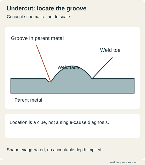
Schematic; source.
Avoid confusing different problems
An incompletely filled groove concerns insufficient weld metal filling the joint. Undercut concerns a groove in the parent metal at a toe. These descriptions direct attention to different locations, even if both appear as a depression.
Burn-through is another distinct observation. Miller's Millermatic 211 manual defines it as melting completely through the base material and leaving holes. Its troubleshooting section treats that separately from incomplete fusion. See OM-265809C, section 9. This March 2016 manual is a documented equipment example, not a universal setup chart for every MIG machine.
Do not diagnose an internal fusion problem from the outer profile alone. TWI explains that lack of sidewall or inter-run fusion involves failure to fuse with the joint wall or a previous bead. Restricted access, preparation, settings and technique can contribute. Its fusion guide explains those mechanisms. A visible groove and incomplete fusion are not interchangeable labels.
Investigate the combination of setup and movement
TWI identifies arc spread, insufficient filling, travel speed, current and torch manipulation among the factors involved in undercut. That combination matters: the same-looking groove does not justify the same adjustment in every joint or welding position.
ESAB's MIG troubleshooting education also discusses undercut in relation to excessive melting and parameter selection, particularly voltage, alongside consistent arc length and gun angles. Read ESAB's MIG defect guide. This is manufacturer education; it does not supply a qualified procedure for your material.
Compare the actual setup with the intended one before changing it. Record the machine and mode, wire designation and diameter, shielding arrangement, joint, material thickness and welding position. Note the displayed settings accurately. Keep any supplier starting guidance attached to the exact wire and machine combination.
For movement, record where access or hand support changed. Our travel-speed and torch-angle lesson helps you separate those observations instead of adjusting several variables together.
Separate investigation from acceptance and repair
Troubleshooting asks why an imperfection appeared. Acceptance asks whether the completed joint meets its specified requirements. TWI points to the applicable standard and job requirements when assessing shape imperfections. There is no universal acceptable depth that this lesson can assign to every weld.
A photograph without a suitable scale or measuring method does not establish the groove's dimensions. Arrange the required examination with someone competent to perform it. Our preparation and inspection manual explains why a tidy surface cannot prove every required property.
Do not cover the groove with another bead or grind it away simply to improve appearance. Any repair must follow the applicable review and repair requirements. Allow samples to cool, isolate equipment before permitted maintenance, and retain the normal exposure controls and protective equipment during investigation.
Hypothetical worked example: locate the change
Imagine a supervised MIG practice exercise on identified mild-steel coupons. A learner notices a groove beside the last portion of the bead. The first portion looks different, although the machine controls were not deliberately changed.
They label the coupon and photograph the transition. During an isolated rehearsal, they notice that a clamp obstructs their hand support near the same point. That is a useful lead, not proof that the clamp caused the undercut.
The instructor reviews the setup, joint and movement before choosing the next exercise. If a movement comparison is appropriate, they keep the documented setup and preparation consistent and change only the agreed part of the rehearsal or technique. They label the next coupon and assess it through the same method.
No successful correction, measured depth or strength result is assumed here. The example shows how to turn a vague complaint into an investigation that can be reviewed.
Practical checklist and self-check
- Identify the groove's position relative to the toe and joint.
- Record its extent and where the appearance changes.
- Retain the setup, consumable and coupon details.
- Check access and movement against the intended procedure.
- Agree on one justified comparison and a consistent inspection method.
- Keep acceptance and repair decisions with the applicable requirements.
Self-check: Does an edge groove prove that voltage alone was too high?
Answer: No. Confirm the imperfection and investigate the documented setup, filling and movement together. A single surface observation does not establish one cause.
Put the choice in context.
Try the welding process finder to narrow your equipment research, or compare a complete setup in the ownership cost calculator.
References
Open the publisher’s page. If a new tab fails, use “Open directly” or copy the address into your browser.
- Miller — Millermatic 211 OM-265809C, March 2016 · See OM-265809C, section 9Opens the source in a new tabmillerwelds.comLink checked · 31 Oct
- TWI — Lack of sidewall and inter-run fusion · Its fusion guide explains those mechanismsOpens the source in a new tabtwi-global.comLink checked · 31 Oct