
In this guide
More MIG welding spatter is a reason to stop and compare the present setup with the last satisfactory practice run. Check what changed before turning several controls. Spatter alone does not identify one fault, and reducing it does not prove that a joint is sound.
Reader question: Why has my MIG weld suddenly started producing more spatter?
Learning objective: Build a useful before-and-after record, separate equipment checks from technique changes, and recognise when the exact machine instructions or qualified help are needed.
What the symptom actually tells you
Spatter consists of expelled molten particles that solidify around the weld. It differs from porosity, which involves gas cavities in weld metal. This lesson concerns gas-shielded wire welding, commonly called MIG/MAG or GMAW; it does not supply a setup for every flux-cored wire. The Millermatic 211 manual, section 9-8, defines spatter and lists several possible causes rather than one diagnostic sign.
Describe the change precisely: did it begin after a spool, tip or gas-cylinder change, or only when reaching a different part of the joint? Write down whether the wire feed also became irregular. “More cleanup than the previous sample” is a more useful observation than “the welder is bad”. Keep the sample label and setup record together.
Check identity and consumables first
Read the wire designation and diameter, gas identification and applicable machine program. Do not substitute a remembered polarity rule for the wire manufacturer's instructions. A machine capable of several processes can still be configured incorrectly for the consumable currently fitted.
Miller's troubleshooting article identifies contaminated material or wire, excessive extension, inadequate shielding and unsuitable or worn contact tips among possible contributors. Its advice is manufacturer education, not a universal procedure. In particular, do not extend its general self-shielded polarity statement to every flux-cored product.
Before inspecting or maintaining the gun, follow the machine's isolation and cooling instructions. Do not open power-source internals. The 2016 Millermatic manual's safety section warns that inverter components can retain hazardous voltage after disconnection. That manual applies to the documented machine revision; use your own model's instructions for actual work.
Separate distance, shielding and settings
Electrode extension is the wire between the contact tip and arc. Contact-tip-to-work distance includes that extension and the arc length. A change in how the gun is held can therefore change the welding condition even when the displayed settings stay unchanged. See our gun-distance lesson before treating every change as a faulty dial.
Check documented gas delivery and whether the nozzle is obstructed; do not automatically increase flow. Maintain fume controls while investigating shielding. UK HSE guidance prioritises avoiding or reducing exposure, extraction at source, and suitable respiratory protection where needed. Blocking a draft is not permission to shut off extraction or continue without an effective control plan.
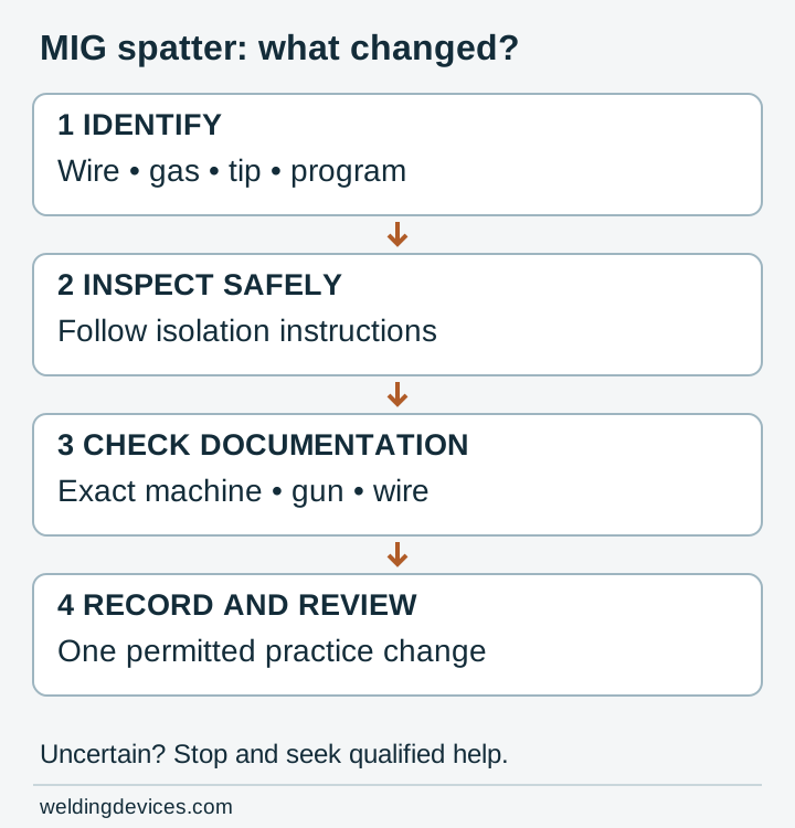
*Investigation sequence, not a machine-setting chart or weld-acceptance test. Read with the Miller troubleshooting guidance and model-specific manual.*
Why inductance is not a magic spatter control
In short-circuit, or dip, transfer the wire repeatedly contacts the pool. TWI explains that inductance slows the rise of current during this cycle. Too little can contribute to spatter; too much can leave the wire stubbing into the work. This explanation concerns dip transfer, not every transfer mode or machine control.
Consequently, “turn inductance up” is not a complete answer. Some power sources manage arc dynamics automatically, while adjustable functions need their own instructions. Record the selected process and program before considering an authorised adjustment. A diagram of the principle cannot determine your dial position.
Hypothetical example: a change after replacing a tip
Imagine supervised practice on identified mild-steel coupons. The learner records increased spatter immediately after fitting a replacement contact tip. The spool, gas and selected program were not intentionally changed.
First, stop and follow the equipment's inspection procedure. Compare the replacement's part identification with the gun documentation and wire size. Record the previous tip identification if known; write “unknown” rather than guessing. Then compare gun distance and other recorded conditions with the earlier session.
If documentation confirms a mismatch, obtain the specified component through the approved maintenance process. Plan a labelled comparison sample with the instructor. No result is assumed: persistent spatter, uncertain identity or another suspect feature means further assessment, not repeated unrecorded adjustments.
Practical checklist and self-check
- Identify machine, wire, gas and process before changing anything.
- Record the last change and when the symptom appears.
- Inspect only after the required isolation and cooling steps.
- Compare consumable identity, condition and distance with applicable instructions.
- Keep protection, extraction and fire precautions in place.
- Agree one permitted practice change; label the sample and record the observation.
Self-check: Spatter increased after changing a contact tip. Should you immediately lower voltage?
Answer: No. Verify the changed component and other conditions first. A symptom is not proof that voltage is the cause. Continue with the MIG/MAG practice manual and workspace preparation checks. Critical or uncertain joints require qualified assessment; this checklist cannot approve them for service.
Put the choice in context.
Try the welding process finder to narrow your equipment research, or compare a complete setup in the ownership cost calculator.
References
Open the publisher’s page. If a new tab fails, use “Open directly” or copy the address into your browser.