
In this guide
The wire stops, the arc splutters, and the next squeeze of the trigger produces a tangle inside the feeder. It is tempting to change voltage immediately. First identify what stopped moving and where. Birdnesting, burnback and slipping describe different observations, even when they happen together.
By the end of this guide, you should be able to distinguish those symptoms, explain the main parts of the wire path and choose a sensible first inspection. This is a lesson in recognising evidence, with your exact machine manual governing maintenance and setup.
Recognise the three symptoms
Birdnesting is wire buckling into a tangled bundle around the drive system. Burnback means wire has fused in or onto the contact tip. Slipping means the drive rolls turn without advancing the wire consistently. These are observations to record before deciding which part needs attention.
Bernard and Tregaskiss explain how disrupted wire feeding can cause an erratic arc, burnback and birdnesting. A tangled wire bundle identifies where wire accumulated; it does not establish why forward movement stopped. Photographing its location before clearing it can help a technician understand the sequence.
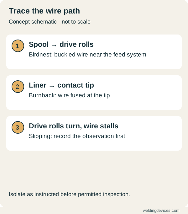
Schematic; source.
Pause before opening the wire path
Stop welding and follow the manufacturer's shutdown and isolation instructions before handling feed components or replacing consumables. Allow hot parts to cool. Do not put fingers near moving rolls or use a hand to obstruct wire as an improvised test. Feeding procedures differ, and pressing the trigger can energise parts as well as move wire.
CCOHS describes the shock hazards of live welding circuits and damaged cables. Damaged insulation, a burning smell or an electrical fault belongs with qualified service. The useful boundary here is simple: inspecting permitted consumables is different from opening a power source to investigate its electronics.
Match drive rolls to the wire
Drive rolls grip and propel wire. Their groove size and shape need to match the consumable and feeder instructions. Hobart's technical guidance distinguishes smooth V-grooves commonly used for solid wire, knurled grooves used for appropriate cored wires, and U-grooves for aluminium and other soft wires.
Pressure matters too. Excessive tension can deform wire; insufficient tension can allow slipping. Turning the tension knob harder every time feeding hesitates can therefore make the problem worse. Check which wire is actually installed, rather than assuming the previous setup still applies.
Hobart explains the relationship between roll selection, tension and wire damage. Use the feeder's specified adjustment procedure. There is no universal tension number that transfers reliably between different feed mechanisms.
Check the liner and contact tip together
The liner guides wire through the gun cable. The contact tip transfers welding current to that moving wire. A kinked, worn or incorrectly sized liner can interfere with travel; an incorrectly installed liner can introduce another feeding problem. Replacing a tip alone will not correct every restriction farther upstream.
Miller also describes contact-tip wear that makes the opening oval, often called keyholing. Poor electrical pickup can then disturb the arc. Match replacement parts to the gun, wire diameter and application, and follow the specified liner installation and trimming method.
Miller's consumables guide explains these liner and contact-tip functions. Before buying parts, note their markings and the gun model. That makes a supplier conversation more useful than asking for a part that merely looks similar.
Aluminium needs its own feeding plan
A setup that feeds steel successfully does not automatically suit aluminium. Aluminium wire has lower column strength and can buckle more readily when pushed through a resistant path. Miller identifies feeding difficulty and birdnesting as important aluminium MIG concerns; interrupted feeding can also lead to burnback.
Miller's aluminium guide puts equipment setup and liner installation in context. Check the machine's supported wire-delivery options before treating extra roll pressure as a solution. For material preparation, continue with our separate aluminium welding guide.
A worked example: keep the evidence useful
Imagine a supervised practice session where an operator changes a wire spool, then experiences intermittent feed and finally a tangle. This is a hypothetical example, not a diagnosis of your machine.
Write down what changed: wire designation, diameter, installed rolls and any consumables replaced. Compare those details with the manual. Record whether the first observation was slipping, a stopped wire at the tip or buckling near the rolls. Keep observations separate from explanations: “rolls turned while wire stopped” is more useful than “the motor is weak.”
After an authorised correction, assess the result using the manual's checks. Changing several unrelated controls together makes it harder to learn what mattered. Repeated faults justify service support rather than repeated resets. Our torch and consumables guide explains the surrounding connections.
A short check before the next session
- Can you name the symptom and its location?
- Do the wire, rolls, liner and tip match the documented setup?
- Have you recorded the last change and the result of the permitted check?
Self-check: Does finding a birdnest prove that roll pressure was too low? Answer: No. It establishes that wire buckled and accumulated. Find the reason using the complete feed path and the applicable equipment instructions.
Put the choice in context.
Try the welding process finder to narrow your equipment research, or compare a complete setup in the ownership cost calculator.
References
Open the publisher’s page. If a new tab fails, use “Open directly” or copy the address into your browser.